Lattice disks

Design and computational evaluation of additively manufactured SS316L disks with internal lattice structures, using the finite element method.

SS316L · L-PBF · ANSYS 2023 R1
Diploma thesis · NTUA · 2024
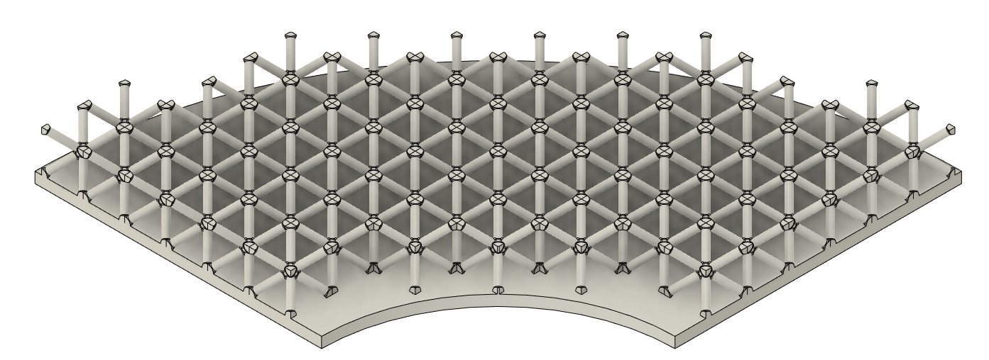
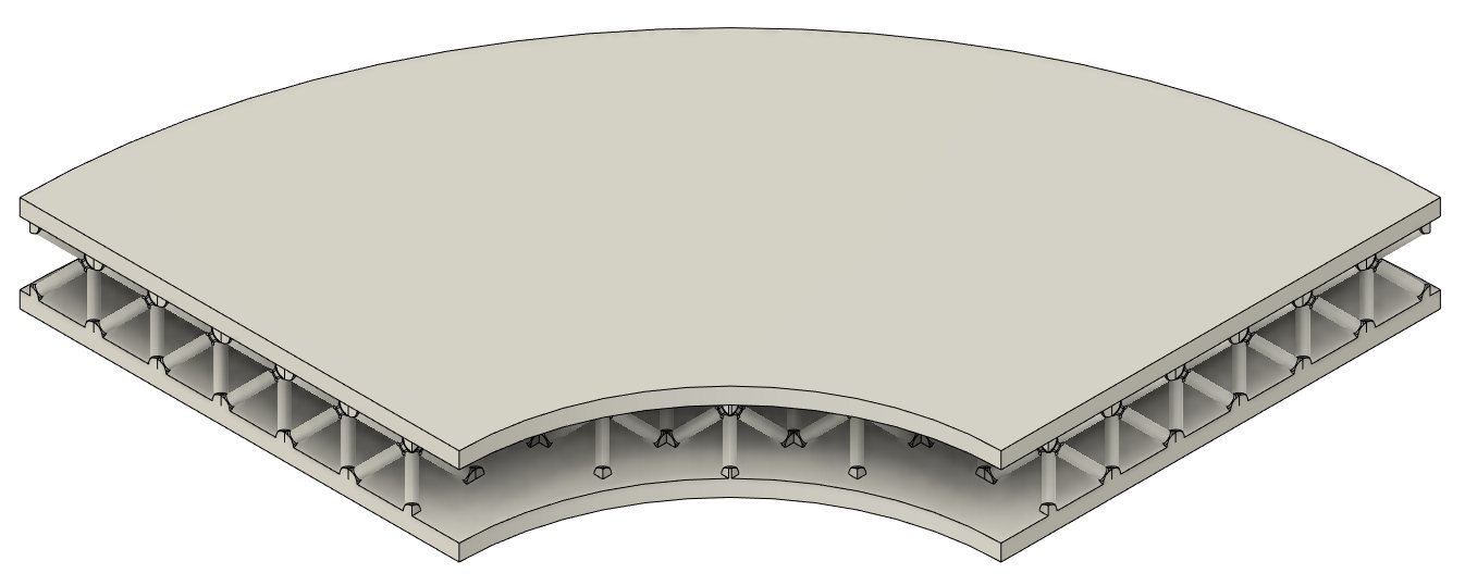
Quarter disk segment with internal lattice between two 1 mm plates, modelled in Fusion 360
Disk segment · two 1 mm plates with an internal lattice
The question

How does the shape of the internal lattice change the way a 3D printed steel disk carries load?

Five lattice disks, built from three unit cells at different densities, were modelled in Fusion 360, meshed and solved in ANSYS under the same compression, then compared on deformation, strain, stress, strain energy and reaction force.

5Lattice variants
3Unit cells
0.5 mmImposed compression
14×Stiffness range
247 kNHighest reaction force

Why lattices

Scope

Weight reduction

Material only where the load path needs it.

Tunable properties

Stiffness and strength set by geometry, fully parameterised.

Decentralised production

Parts made on demand, close to where they are used.

Rapid prototyping

From model to tested part without tooling.

Lower cost and lead time

No moulds, fewer steps, faster iterations.

Lower environmental impact

Less material, less waste, more efficient parts.

Three unit cells

At different densities
Body-centred cubic unit cell, 12% density
12%
Body-centred cubic unit cell, 50% density
50%
BCC · 12% and 50%

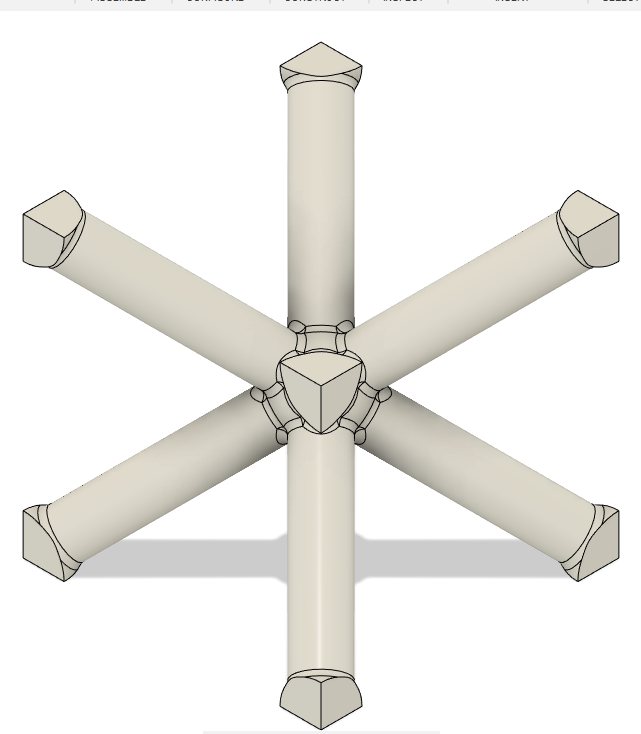
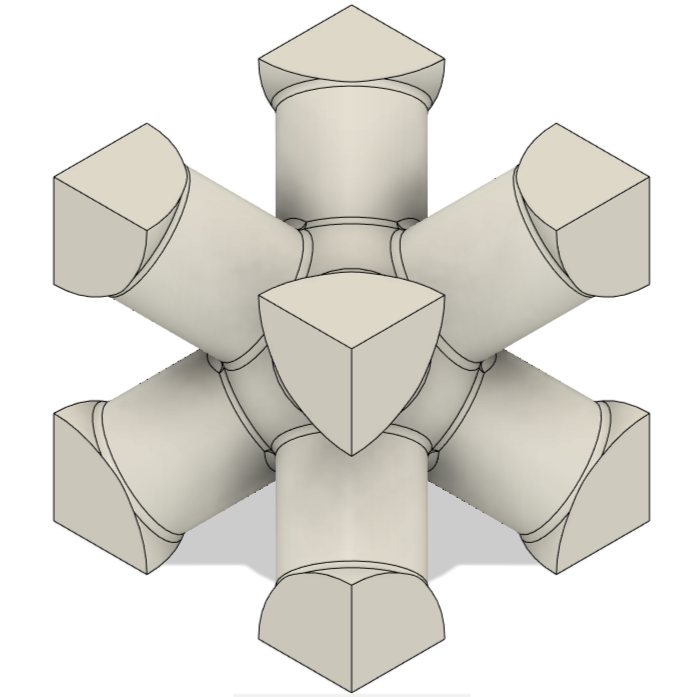
Body-centred cubic

  • Uniform struts, equal in every direction
  • Nodes keep a fixed orientation relative to each other
  • Nodes treated as rigid; node centres follow an affine displacement field
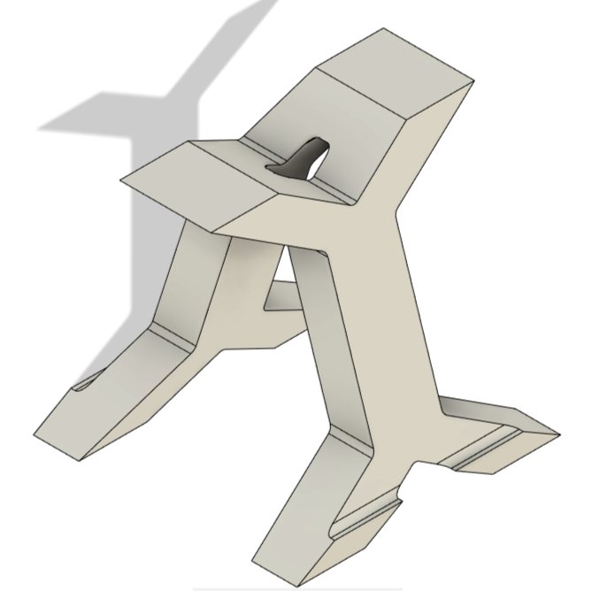
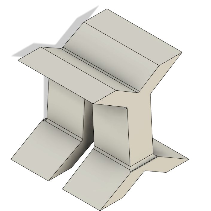
I-type unit cell, 12% density
12%
I-type unit cell, 30% density
30%
I-type · 12% and 30%

I-type

  • Structural integrity without nodes
  • Lower squeal propensity in the 4–8 kHz range
  • Simple to design and to manufacture
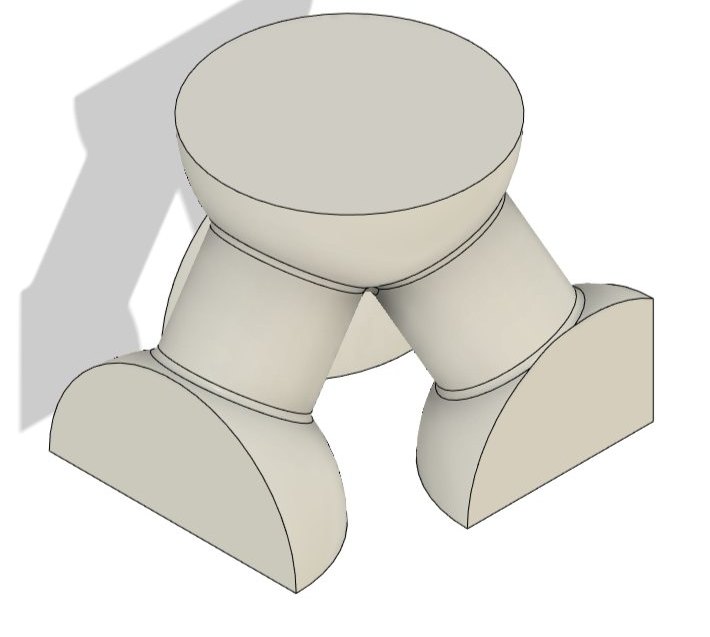
Tetrahedral unit cell, 50% density
50%
Tetra · 50%

Tetrahedral

  • Lightweight, with a high strength-to-weight ratio
  • Shear response stays linear up to failure
  • Fails suddenly once shear stress reaches a critical threshold

Method

Model · mesh · load · material
  1. Lattice generationFusion 360

    Each unit cell is patterned across a 90° disk segment and joined to a 1 mm plate above and below.

    Lattice of BCC unit cells patterned on the bottom plate
  2. MeshANSYS

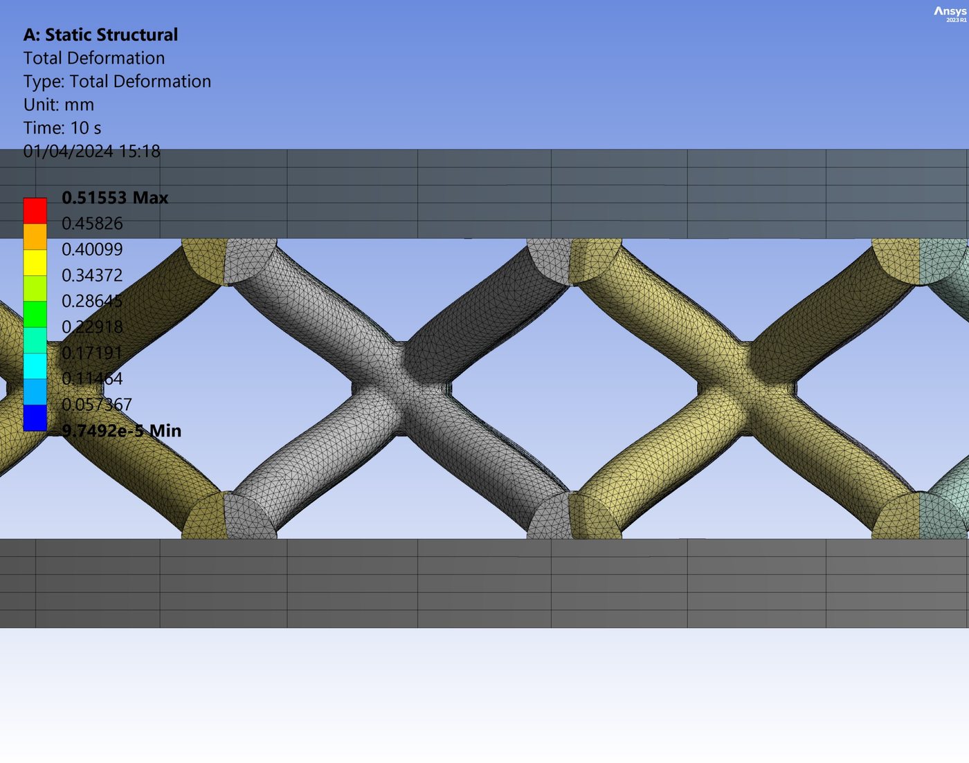
    Plates meshed with 40 angular and 3 axial divisions across the 1 mm thickness. Struts, nodes and fillets get their own face sizing, refined until the maximum deformation changes by less than 0.1% between steps.

    ANSYS mesh close-up of the BCC struts between the plates
  3. Boundary conditionsAfter Barros et al., 2020
    • Radial sides of the segment fixed in x and y
    • Bottom face of the bottom plate fixed
    • Top face of the top plate displaced gradually by 0.5 mm
    Side view of an I-type 12% lattice between the plates
  4. MaterialStainless steel 316L · L-PBF
    • Proven in laser powder bed fusion
    • Corrosion resistant, for harsh environments
    • Biocompatible, used for implants and surgical tools
    • Strong, ductile and weldable, with few defects in complex shapes
    SS316LFe · Cr 16–18% · Ni 10–14% · Mo 2–3%

Results

Same 0.5 mm compression for every disk

Peak values are local maxima of the simulation.

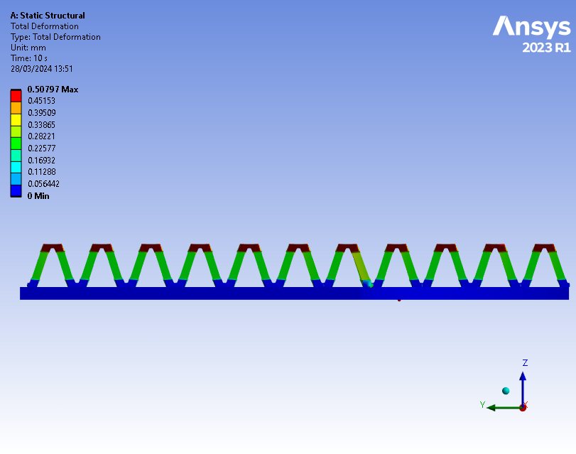
Contour maps

ANSYS · static structural

What the numbers say

Findings
  1. Density drives stiffness. Going from 12% to 50% density multiplies the BCC disk's reaction force by 11, from 17.4 to 191.6 kN. The I-type disk doubles from 12% to 30%, from 37.0 to 77.4 kN.
  2. The tetrahedral cell is the stiffest. At 50% it carries the highest reaction force, 246.7 kN, and stores the most strain energy, 100.4 J, about 14 times the force of the BCC 12% disk.
  3. BCC spreads the load most evenly. BCC 12% has the lowest peak von Mises stress, 1,054 MPa, and the lowest average, 307 MPa.
  4. The I-type concentrates stress. It reaches the highest peak stress, 2,118 MPa at 12% density, even though its average stays close to the others.
  5. Same compression, different effort. All five disks deform 0.50–0.52 mm at most, because the load is a fixed displacement. The differences show in the force needed, the stress and the stored energy.

Next steps

  • Lattice structures in conventionally manufactured materials
  • Relationship between lattice density and mechanical properties
  • Cartesian versus cylindrical lattices
  • Fully parameterised mechanical properties
  • Further lattice patterns
  • Torsional and shear loading
  • Larger displacement scenarios
  • Physical compression tests
  • Fatigue testing of lattice clutch disks for long-term durability

Credits

Author
Sotirios Vlogiannitis, Mechanical Engineer MEng, NTUA · founder of OGCODE
Supervision
Prof. Vasileios Spitas and Dr Nikolaos Rogkas
Institution
National Technical University of Athens, School of Mechanical Engineering, Section of Mechanical Design and Control Systems, 2024
Tools
Autodesk Fusion 360 for the lattice models, ANSYS 2023 R1 static structural for the analysis
Work with us

Need a lighter part, a lattice or an FEA check?

We design lattice structures, simulate them and produce them in polymer or metal. Or learn how to do it yourself.

Contact

Got a part in mind?

Send a sketch, a reference photo or a 3D file, then choose the material, the size and your deadline.